Automated control system
MIDIEL Group completes the manufactured hoisting machines with an automated control and monitoring system include built-in data logger (SAUKiRP-PM) of its own design. In addition, SAUKiRP-PM is proposed to replace obsolete relay-contactor control systems of existing hoisting machines. The operation of the hoisting machine is controlled from the automated workplace of the driver – the mine hoisting control desk.
Distinctive features of SAUKiRP-PM are:
- use of modern programmable logic controllers (hereinafter referred to as PLC) Simatic S7 – 1500, S7 – 1200;
- dual-channel system architecture;
- availability of a modern developed human-machine interface system; the ability to work with AC drives (short-circuit rotor asynchronous motor, controlled by a frequency converter, synchronous motor controlled by a frequency converter,
- induction motor with a phase rotor controlled by a rotary station), direct current (thyristor converter-motor, generator-motor) using hardware signals and/or data bus (Profibus, Profinet, CAN);
- the ability to control brake systems of disc and radial-shoe type using hardware signals and / or data bus (Profibus, Profinet, CAN);
- integrated data logger based on IBA Pda hardware and software complex.
Structurally, SAUKiRP-PM consists of two channels connected by communication buses. Each of the channels is an independent PLC with connected signal I/O devices, sensors and controls. When executing the control program, the PLC analyzes the signals from the sensors and controls and generates the control signals of the hoisting equipment. To implement the concept of dual-channel, the control of critical parameters of the lifting unit is carried out by both channels using twice the number of sensors. In this case, the signals received from the sensors, as well as the control signals generated in the first and second channels, are subject to equivalence control. Thus, the serviceability of both channels of the control system is monitored. SAUKiRP-PM uses PLCs of different models of the same family. This allows you to implement protection against erroneous program execution due to errors in the system software or with a hardware malfunction of the PLC. When they appear, there is a mismatch of control signals, which is recognized by the equivalence control subroutine.
Block diagram of the automation system
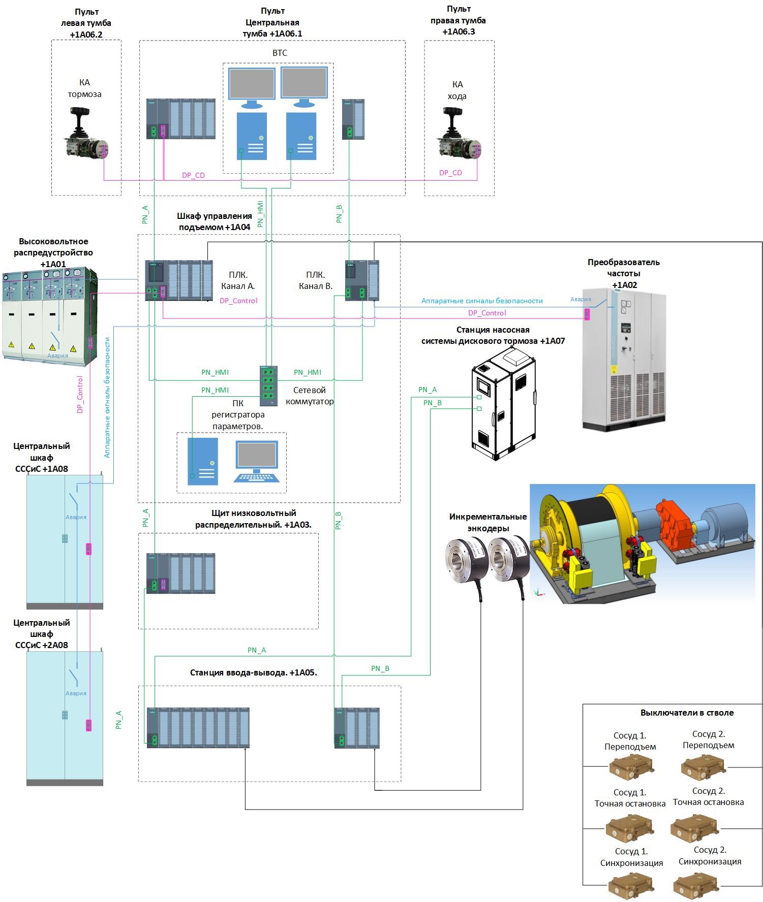
SAUKiRP performs the functions of interconnected control of the main drive, brake and all other mechanisms of the lifting installation, control of their operation, implements all the functions of protections and interlocks required by the Safety Rules, including:
- Input and storage of hoist unit parameters (hoist depth, coordinates of track sensors, etc.) required for control set-up;;
- input and storage in memory of working and protective diagrams for various modes of operation;
- calculation of the task for the speed of rotation of the electric drive;
- electric drive control;
- brake control;
- control of the current speed by means of two independent channels and two independent speed sensors; determination of the
- current position of the vessels according to the readings of the pulse counters of two independent channels and track sensors connected to each of the channels;
- continuous comparison of the actual values of the position velocity determined in each of the channels with each other; automatic deceleration
- call, signaling the beginning of the deceleration period;
- overspeeding protection;
- protection against overlifting;
- reverse protection;
- protection against slipping and signaling of slippage of ropes (for SHPM with a friction pulley);
- other protections and interlocks due to the requirements of industrial safety and the specifics of the equipment;
- generation of messages about the triggering of protections or violation of control functions.
The SAUKiRP-PM includes the following devices::
- lifting control cabinet (PWC) in which the PLC of channel A, the PLC of channel B, and the parameter recorder are placed;
- low-voltage switchboard (SCHNR), in which the starting and shield equipment and uninterruptible power supplies are located;
- input-output station (I/O) for connecting sensors and actuators located in the machine room; a
- mine hoisting operator’s console (PM) with a video terminal station (MTC) integrated into it;
- Apparatus for protection and control of movement (PL according to the customer’s requirement)
- engineering station (IS);
- A set of sensors and special cables.
The design solutions of the cabinet equipment, the driver’s console are individual for each lifting unit, taking into account the purpose of the PM and the special requirements of the customer.
Gallery of design solutions SAUKiRP-PM
")


")
")
")
")
")
")
")
")
")
")
")

The control system provides the following operating modes of the lifting unit in accordance with the purpose:
- semi-automatic mode of operation (for cage or skip hoisting installations), in which the start of movement is carried out by the driver, and the further execution of the cycle and the stop of the machine occurs automatically;
- automatic mode of operation (for skip hoisting unit), in which the start of movement is carried out by the signal of the automated skip loading system, further execution of the cycle and stopping of the machine occurs automatically; manual mode of operation of the lifting machine, in which the setting of the speed and direction of movement of the vessel, as well as the magnitude of the
- braking torque, is carried out by the driver using the handles of the command apparatus for setting the stroke and brake. The magnitude of the velocity is defined as the smallest (modulo) of the velocity calculated on the basis of the motion diagram for a given point of the path and direction of movement and the velocity given by the stroke command apparatus
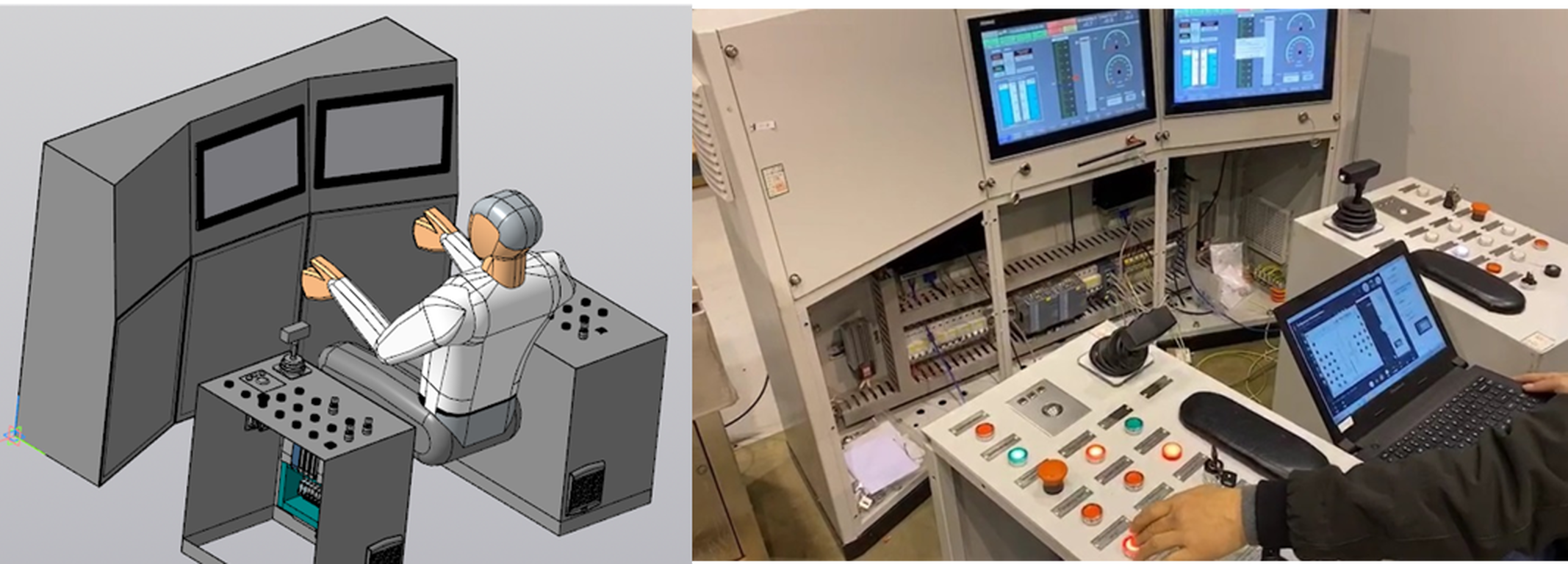
The operation of the hoisting machine is controlled from the remote control of the mine hoisting operator, which includes the following components:
- the driver’s workplace, consisting of two pedestals with a chair installed between them;
- panel of monitors of the video terminal station (BTC).
On the upper horizontal and inclined surfaces of the pedestals there are controls and alarms (buttons, switches, switches, indicators, sound alarms). On the right pedestal there is a command apparatus for controlling the task of the stroke in manual mode, on the left – a command apparatus for controlling the brake in manual mode. On the pedestals of the console there are also means of voice and telephone communication with other workplaces of the lifting unit.
On the pedestals of the console there are also means of voice and telephone communication with other workplaces of the lifting unit. On the left pedestal there is a panel of voice radio communication with a vessel, on the right pedestal there is a microphone, a speaker for loud-speaking wired communication with workplaces and a telephone.
In front of the driver there is a panel of monitors with two or three (in the case of industrial television) monitors installed on it. On the two monitors that are part of the BTC, the status of the lifting unit is displayed. The third monitor is included in the industrial television system and is installed as needed .
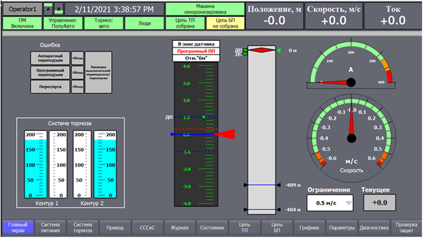
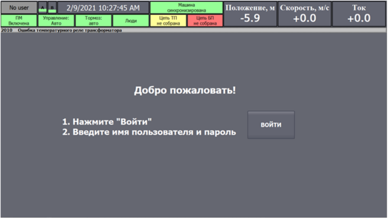
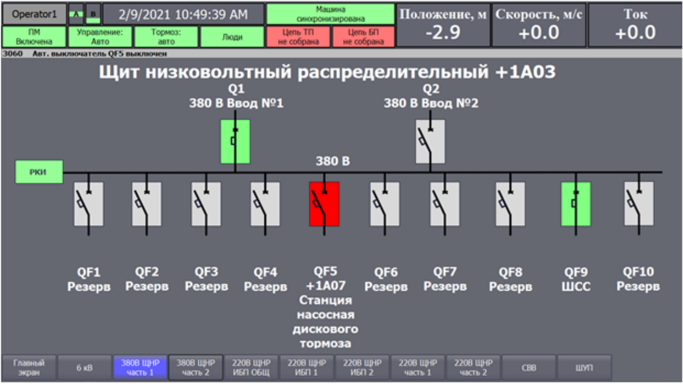
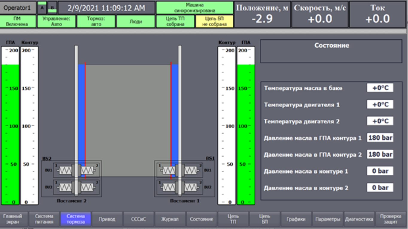
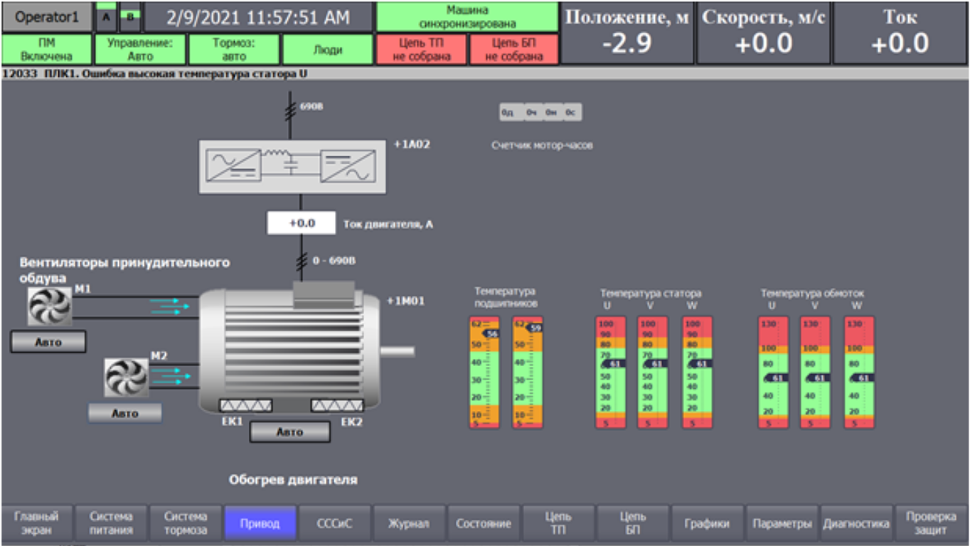
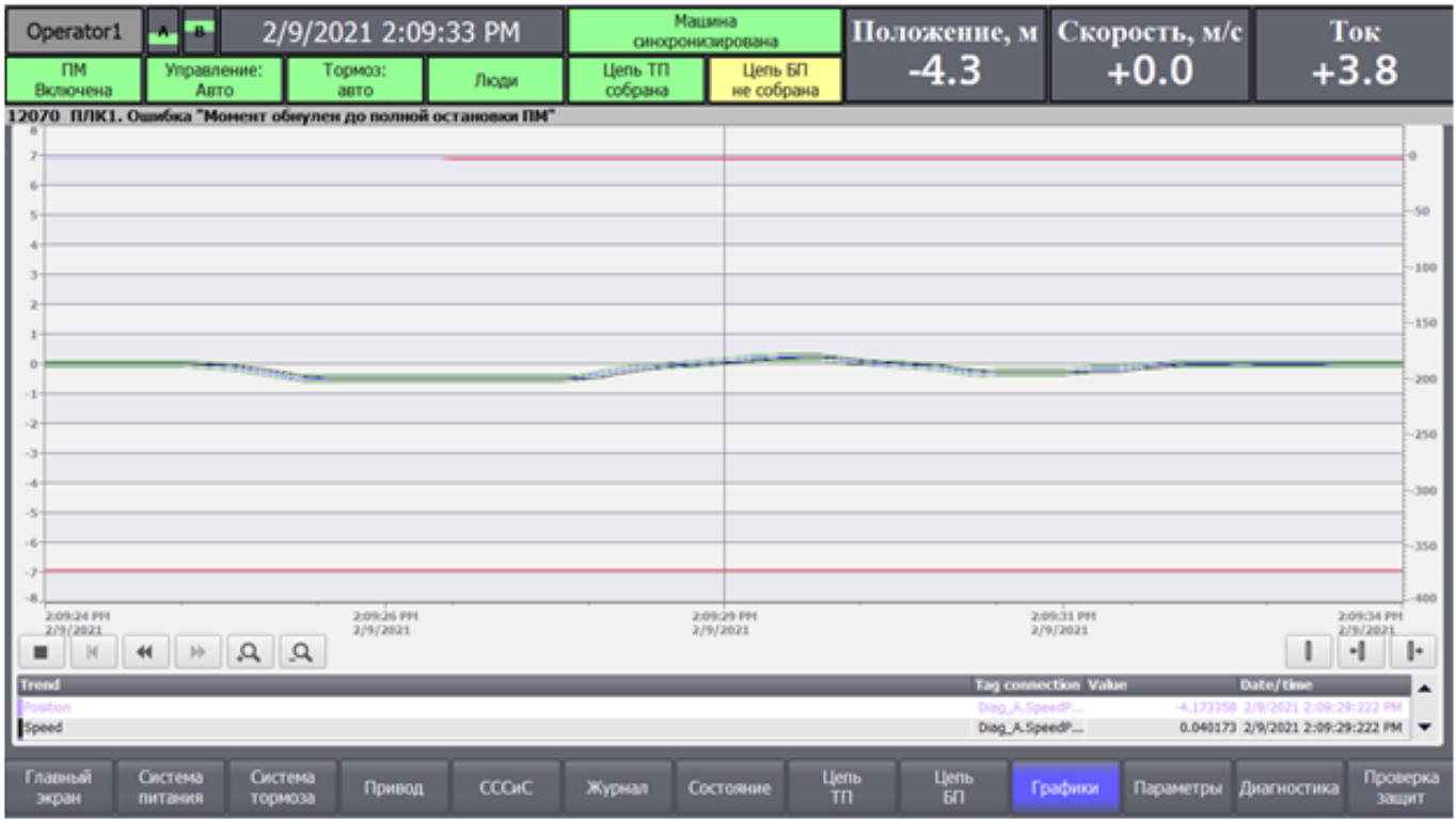
Screen forms of the video terminal station


Design
Application of modern computer design programs EPLAN Electric P8 and AutoCAD Electrical
Manufacturing
The equipment is manufactured at one of the enterprises of Ukraine or the EU according to the design documentation of the MIDIEL Group. Components from leading European manufacturers are used.